


MIL-STD-461G Magnetic Shielding Guide: Passing RE101 Through Engineered Field Control
Posted by Josh Wickler, Vice President of R&D on Nov 10th, 2026
Key Takeaways
- Conventional Shielding Fails:* Standard RF shielding materials like aluminum and copper are ineffective for MIL-STD-461 RE101 (30 Hz to 100 kHz) because their skin depth at these low frequencies is too large to provide meaningful magnetic attenuation.
- Permeability is Fragile:* High-permeability alloys like MuMETAL® are required, but fabrication processes like bending and welding collapse their magnetic permeability by up to 99%. Performance is only recovered through a final, post-fabrication dry hydrogen annealing cycle.
- Geometry Dictates Leakage:* An enclosure built from properly annealed material can still fail RE101 if apertures, seams, or cable penetrations interrupt the low-reluctance path for magnetic flux. Shielding collars and welded seams are critical design elements.
- Shielding is an Engineered System:* Passing RE101 is not a material purchase; it is an engineered process that integrates alloy selection, enclosure geometry, disciplined fabrication, final annealing, and validation testing.
- Simulate Before You Fabricate:* Finite-element simulation (COMSOL Multiphysics) can predict B-field leakage at the 7 cm RE101 measurement boundary, but only if the model uses accurate, measured B-H curve data for the post-annealed alloy.
An engineering team designs a shielded enclosure for a new avionics power supply. Confident in their RF shielding experience, they specify 1.58 mm (.062") aluminum, run their far-field calculations, and build the prototype. At the EMI test laboratory, the enclosure passes RE102 radiated emissions testing with margin. But when the technician positions the loop antenna for the RE101 magnetic emissions test, the spectrum analyzer shows a failure at 60 Hz and its harmonics.
This scenario is common. It highlights a critical distinction often missed by teams new to military compliance: MIL-STD-461 is not a single test, and the physics that govern high-frequency electric field control are irrelevant to low-frequency magnetic field control.
For magnetically demanding tests especially RE101 compliance is fundamentally a shielding design and material science problem. This article provides a practitioner's guide to the engineering decisions that determine whether your equipment passes or fails, focusing on the test that most often surprises unprepared programs. We will cover the physics of RE101, enclosure design discipline, material and annealing requirements, and simulation-based pre-validation needed to meet the standard.
What MIL-STD-461G Governs and Where Magnetic Shielding Enters the Picture
MIL-STD-461G establishes the electromagnetic interference (EMI) emission and susceptibility requirements and verification test methods for electronic, electrical, and electromechanical equipment and subsystems procured by the U.S. Department of Defense. This standard, dated December 2015, supersedes all prior revisions for new defense contracts.
The tests are organized into four categories:
- Conducted Emissions (CE): Unwanted signals on power and signal lines.
- Radiated Emissions (RE): Unwanted fields radiated into space.
- Conducted Susceptibility (CS): Equipment vulnerability to unwanted signals on power and signal lines.
- Radiated Susceptibility (RS): Equipment vulnerability to fields radiated through space.
Crucially, not all tests apply to every program. Per MIL-STD-461G Section 4.2, the procuring activity's Statement of Work (SOW) or contract "tailors" the standard, specifying which tests are required for a given platform. Because a single failed test at a qualified EMI test laboratory can delay a defense program milestone by weeks or months, understanding which requirements apply before fabrication is essential.
Among these tests, two directly require magnetic field control:
- RE101: Radiated Emissions, Magnetic Field (30 Hz to 100 kHz)
- RS101: Radiated Susceptibility, Magnetic Field (30 Hz to 100 kHz)
While both are important, RE101 is the test most frequently underestimated because it operates in a frequency regime where conventional RF shielding materials like copper and aluminum provide negligible attenuation.
The Physics Behind RE101's Compliance Challenge
RE101 measures the magnetic flux density radiated from the equipment under test (EUT) and its associated cabling. It is performed at a 7 cm standoff distance using a loop antenna, with limits specified in decibels referenced to one picotesla (dBpT) across a frequency range of 30 Hz to 100 kHz. This near-field, low-frequency measurement regime is where most enclosure designs fail not because the enclosure lacks shielding, but because the material chosen cannot attenuate magnetic fields at these frequencies.
RE101 Test Setup, Limits, and What the 7 cm Standoff Means for Enclosure Design
The RE101 test configuration, detailed in MIL-STD-461G Section 5.16, places the EUT on a ground plane. A rectangular loop antenna sensor probe is then positioned 7 cm from the EUT boundary. The technician methodically moves the probe around the EUT to map the B-field leakage and identify the point of maximum emission for each face.
The 7 cm standoff distance is the key detail. This is a near-field measurement. The sensor is so close to the source that the radiated energy has not yet formed a propagating plane wave with a fixed impedance. In the near field of a magnetic source (like a transformer or power inductor), the magnetic field component dominates. This means that electric-field shielding the Faraday cage effect that works so well for RF is irrelevant here. RE101 is measuring the actual magnetic flux density leaking from the enclosure.
This contrasts sharply with RE102, which measures electric-field emissions from 10 kHz to 18 GHz at a 1 meter distance a fundamentally different physical regime where conductive shielding is effective.
Skin Depth at RE101 Frequencies: Why Copper and Aluminum Cannot Solve This Problem
At low frequencies, magnetic field attenuation is achieved through two mechanisms: absorption loss and reflection loss. For the magnetic fields in the RE101 band, absorption loss within the shield material is the primary factor, and it is governed by skin depth.
Skin depth is the distance into a material at which an electromagnetic field's intensity falls to 1/e (about 37%) of its surface value. For a material to be an effective shield, its thickness must be several times its skin depth.
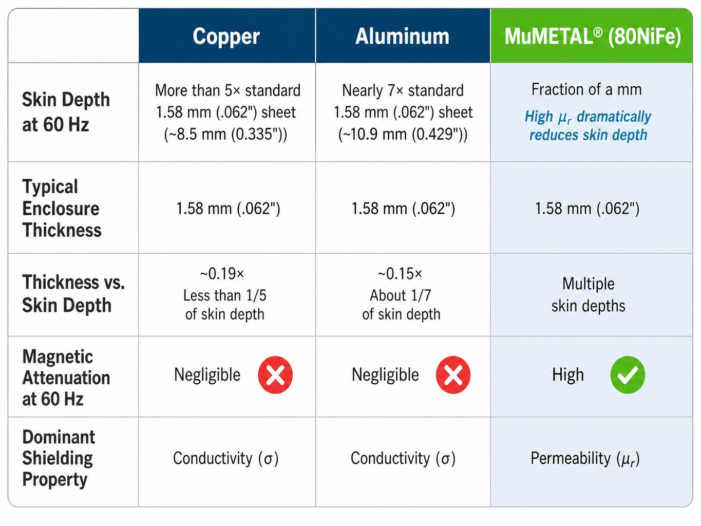
Consider the skin depth of common conductive materials at 60 Hz, a frequent source of RE101 failures from power supplies:
- Copper: More than five times the thickness of standard 1.58 mm (.062") sheet
- Aluminum: Nearly seven times the thickness of standard 1.58 mm (.062") sheet
As a result, a conventional aluminum or copper enclosure provides almost no magnetic attenuation at power-line frequencies.
This is where high-permeability 80NiFe alloys, such as MuMETAL®, become necessary. For these materials, high relative permeability (μr) dramatically reduces skin depth. Even though their conductivity is lower than copper's, the permeability term dominates, resulting in a skin depth measured in fractions of a millimeter at the same frequencies. For RE101 shielding, permeability is the critical material property, not conductivity.
How Apertures, Seams, and Cable Penetrations Defeat Otherwise Sound Enclosures
A shielding enclosure is only as effective as its weakest magnetic-flux path. In practice, that path is almost always an aperture, a seam, or a cable penetration not the wall material itself. An enclosure built from properly annealed MuMETAL® can still fail RE101 if a ventilation slot, connector cutout, or untreated cable entry allows magnetic flux to leak through the enclosure boundary and reach the 7 cm measurement probe.
Aperture and Seam Leakage: Geometry Rules That Map Directly to RE101 Flux Control
Magnetic flux, like current, follows the path of least resistance (or in this case, lowest reluctance). Any hole or gap in a high-permeability enclosure interrupts that low-reluctance path with a high-reluctance air gap, allowing flux to leak out.
The amount of leakage is governed by the aperture's longest dimension. A long, narrow slot leaks far more magnetic flux than a round hole of the same area. A seam or joint in a high-permeability enclosure does not simply reduce shielding by a fixed number of dB; it creates a reluctance discontinuity whose effect depends on the orientation of the incident field relative to the seam.
Practical design rules for RE101 compliance include:
- Keep the longest dimension of any single aperture as small as possible.
- For ventilation, use a pattern of multiple small, round holes instead of one large slot.
- Ensure seam joints maintain continuous magnetic contact. Bolted butt-joints create air gaps that severely degrade shielding. Overlapping joints are better, but welded seams are best. Because MuMETAL® is weldable, it's possible to create a continuous, high-permeability enclosure free of the flux leakage paths that bolted seams introduce. Copper, by contrast, is difficult or impractical to weld.
Read more: Magnetic Shielding Efficiency for Wiring Applications - Magnetic Shield Corporation
Shielding Collars for Cable Penetrations
Cable penetrations are one of the most common failure points in RE101 testing. A simple hole cut for a cable bundle acts as a magnetic window. The solution is a shielding collar: a tube or flange made of high-permeability material that extends outward from the enclosure wall around the penetration.
The design rule is critical: the collar must extend outward by a distance equal to or greater than the longest edge of the aperture or hole diameter.
This geometry creates a high-permeability path that intercepts leakage flux, guiding it along the collar and away from the 7 cm RE101 measurement boundary. Without an effective collar, magnetic flux leaks through the cable hole, causing a localized failure. As with the main enclosure, the collar material must also be properly formed and annealed to achieve its specified permeability.
Material Selection and Permeability Recovery for RE101 Shielding Enclosures
Material selection for RE101 shielding is not a catalog lookup. It depends on the interaction of field frequency, required attenuation, enclosure geometry, and, most importantly, post-fabrication processing. Specifying an alloy without specifying its final processing condition is an incomplete engineering decision that often leads to test failure.
Matching Alloy Properties to RE101 Frequency and Field Requirements
For the 30 Hz to 100 kHz RE101 frequency range, absorption loss governed by skin depth is the primary attenuation mechanism, and in 80NiFe alloys it is high permeability that reduces skin depth. This makes relative magnetic permeability the dominant material parameter.
-
MuMETAL®: This 80Ni5Mo15Fe alloy, conforming to ASTM A753 Alloy 4, is commonly specified for low-frequency magnetic shielding. After fabrication, a proper dry hydrogen anneal increases its permeability by 40–400 times over the stressed, fabricated state, providing high attenuation for low-intensity fields. It is available in thin foil and sheet gauges from .05 mm (.002") to 5 mm (.197").
-
NETIC®: In applications with strong background DC or low-frequency AC fields that risk saturating a single layer of MuMETAL®, a composite shielding approach is required. NETIC® alloy, a high-saturation soft iron alloy, is used as an outer layer. It absorbs the bulk of the magnetic flux without saturating, reducing the field intensity to a level that the inner MuMETAL® layer can effectively attenuate.
Why Fabrication Destroys Permeability and How Hydrogen Annealing Recovers It
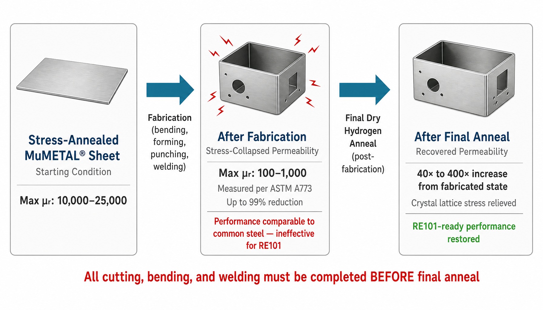
Permeability loss during fabrication is a central consideration in designing magnetic shields for RE101. The high permeability of alloys like MuMETAL® is a direct result of their crystalline structure. Any mechanical stress bending, forming, punching, welding, or even dropping the part introduces dislocations into this structure, causing permeability to collapse.
The measured values show the scale of the effect:
- A sheet of stress-annealed MuMETAL® may have a maximum relative permeability of 10,000–25,000.
- After fabrication, the mechanical stress from forming operations can cause that permeability to fall to as low as 100–1,000, as measured per ASTM A773 a reduction of one to two orders of magnitude.
An enclosure fabricated from MuMETAL® that does not undergo a final anneal may have permeability no better than common steel, rendering it ineffective for RE101.
The solution is a final dry hydrogen anneal, performed after all mechanical fabrication is complete. This high-temperature heat treatment, performed in a controlled atmosphere, relieves the stress in the material's crystal lattice and restores its magnetic properties. This is why the fabrication sequence is paramount: any rework after the anneal reintroduces stress and requires another annealing cycle.
Using Simulation to Predict RE101 Compliance Before Fabrication
Fabricating and annealing a complex MuMETAL® enclosure represents a significant investment in time and cost. Discovering a design flaw at the EMI test lab forces a cycle of redesign, re-fabrication, and re-annealing that can severely impact program schedules.
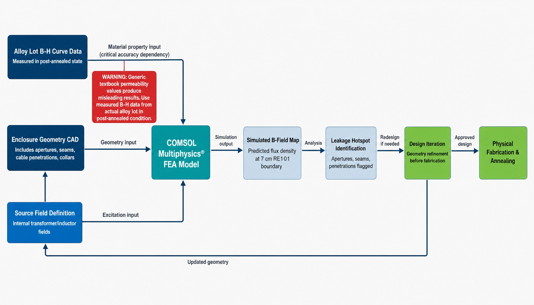
Finite-element analysis (FEA) using tools like COMSOL Multiphysics® can mitigate this risk. A simulation can model the magnetic flux distribution around a proposed enclosure geometry, predict B-field levels at the 7 cm RE101 measurement boundary, and identify potential leakage hotspots at apertures, seams, and penetrations before any metal is cut.
However, a critical caveat applies: the accuracy of the simulation is entirely dependent on the quality of the material property inputs. Using generic, textbook permeability values for MuMETAL® will produce misleading results. An accurate prediction requires the specific B-H curve and saturation characteristics of the alloy lot being used, measured in its final, post-annealed state. A simulation that predicts compliance based on an ideal permeability of 300,000 may not match reality if the fabricated part has residual stress or if seams are not modeled correctly.
Simulation is a powerful risk-reduction tool, not a substitute for physical testing.
From Alloy Selection Through Annealed, Tested Shields: How Magnetic Shield Corporation Supports RE101 Compliance Programs
The core challenge of RE101 compliance is clear: success depends on the integrated control of alloy selection, enclosure geometry, fabrication discipline, final annealing, and pre-test validation. Most supply chains fragment these steps across a material vendor, a sheet-metal fabricator, a heat-treatment subcontractor, and a test laboratory.
Magnetic Shield Corporation's process includes:
- Proprietary Alloys: The company manufactures its own MuMETAL®, Co-NETIC®, and NETIC® alloys.
- Custom Fabrication: In-house capabilities include precision forming, punching, and welding to create complex enclosures with integrated shielding collars and continuous seams.
- Perfection Annealing: Final dry hydrogen annealing is performed in company-operated controlled-atmosphere furnaces after all fabrication is complete, relieving fabrication stress and restoring the alloy's annealed permeability.
- Simulation & Testing: COMSOL Multiphysics® simulation services use B-H data measured in the company's quality laboratory. Shield performance is validated using Helmholtz coils and magnetic field sensors, with testing aligned to ASTM A773, ASTM A698, and other standards.
This integrated process is intended for programs where RE101 compliance requires engineered magnetic shielding, with alloy permeability, enclosure geometry, and final annealing controlled as a single system.
If your program faces an RE101 requirement, contact our engineering team to discuss alloy selection, enclosure geometry, and annealing.
Conclusion
MIL-STD-461G covers a broad range of emission and susceptibility requirements. While many of its tests fall within the familiar realm of RF engineering, RE101 demands a fundamentally different approach grounded in material science and magnetics. Compliance is not achieved by selecting a material from a catalog; it is achieved by engineering the interaction of alloy permeability, enclosure geometry, aperture control, fabrication sequence, and post-fabrication annealing into a system that reliably controls magnetic flux.
The underlying physics set fixed constraints. Conventional conductive shields fail at RE101 frequencies. High-permeability alloys are necessary, but their performance is destroyed by mechanical stress and must be recovered by a final hydrogen anneal. Even a perfectly processed shield will fail if its geometry is compromised by untreated apertures and seams. The earlier in the design cycle that shielding is treated as an engineered system, the lower the risk of an RE101 failure at the test laboratory and the redesign cycle that follows.
Frequently Asked Questions
Does MIL-STD-461G replace all previous revisions for new defense contracts?
Yes, MIL-STD-461G, dated December 2015, is the current revision specified for new Department of Defense procurements. However, existing contracts may still reference earlier revisions (like E or F) unless the contract is formally amended. The procuring activity's Statement of Work (SOW) always dictates the applicable revision and specific tests required for a given program.
Can you weld high-permeability 80NiFe shielding enclosures without permanently degrading magnetic performance?
Yes, MuMETAL® is readily weldable. While the welding process introduces localized stress that temporarily reduces permeability in the heat-affected zone, a final dry hydrogen annealing cycle performed after all welding is complete recovers the permeability lost in that zone, including at the welded joints. The critical discipline is to complete all mechanical fabrication and welding before the final anneal.
What is the correct sensor placement distance for MIL-STD-461G RE101 testing?
The RE101 test procedure specifies that the rectangular loop antenna sensor probe is positioned 7 cm from the boundary of the equipment under test (EUT). The probe is moved to multiple locations to find the point of maximum magnetic flux density. This 7 cm standoff makes RE101 a near-field measurement, where the enclosure's magnetic leakage at that short distance determines compliance.
Is MIL-STD-461 RE101 relevant to quantum computing or sensitive laboratory environments?
Yes. The RE101 frequency range (30 Hz to 100 kHz) covers common sources of magnetic interference that degrade sensitive instruments. Quantum computers, SQUID magnetometers, electron microscopes, and other precision systems often require ambient magnetic fields far below the RE101 limits. The shielding principles high-permeability alloys, aperture control, and final annealing transfer directly to these demanding scientific and high-tech applications.
What is the MIL-STD-461G tailoring process and how does it affect which tests apply?
MIL-STD-461G Section 4.2 requires the procuring activity to "tailor" the standard by specifying which individual tests (e.g., CE101, RE101, RS103) are applicable to a given procurement. This is documented in the contract or SOW and can include modified limits or frequency ranges. Not all tests apply to all platforms; for instance, RE101 is typically required for Navy ships but may be waived for certain ground vehicle programs.
What are the most common reasons equipment fails MIL-STD-461 RE101 testing?
The most common failure modes are: (1) using copper or aluminum enclosures, which have insufficient magnetic permeability at RE101 frequencies; (2) specifying a high-permeability alloy but omitting the final hydrogen anneal after fabrication, leaving permeability collapsed by stress; (3) allowing oversized apertures, unsealed seams, or unshielded cable penetrations that create flux leakage paths; and (4) underestimating the magnetic field strength from internal power components.