


How to Shield a Magnetic Field: A System Design Guide for Engineers
Posted by Josh Wickler, Vice President of R&D on Oct 16th, 2026
Key Takeaways
- Magnetic shielding works by diverting magnetic flux through a high-permeability material (like MuMETAL®), not by blocking it. This mechanism is distinct from electric-field or RF shielding.
- Before selecting a material, you must characterize the ambient field's source type (DC/AC), frequency, magnitude, and orientation using a calibrated three-axis fluxgate magnetometer.
- The permeability of alloys like MuMETAL® (ASTM A753 Alloy 4) can fall by one to two orders of magnitude due to fabrication stress. Final dry hydrogen annealing after all forming and welding is not optional; it is the step that restores shielding performance.
- Enclosure geometry, aspect ratio, and multi-layer nesting contribute as much to performance as the material itself. Every aperture for cables or access requires a collar to prevent field reentry, which often limits the shield's final attenuation.
- Validate performance with a two-stage approach: laboratory insertion-loss testing in a Helmholtz coil to verify the part, and an in-situ field survey to confirm performance in the final operating environment.
An engineering team installs a nickel-iron shield around a sensitive magnetometer inside an aerospace instrument bay. Based on the alloy's datasheet, they expect at least 40 dB of attenuation. Once the unit is integrated, however, they measure only 8-12 dB. The shield is formed from pre-annealed sheet, drilled for cable penetrations, and bolted into a mounting bracket all standard fabrication steps. But two critical processes are missed: final hydrogen annealing and proper aperture management.
This scenario is not an outlier; it is a routine failure mode. Learning how to shield a magnetic field is not a material-selection problem alone. It is a system-design problem where the interaction among field characterization, alloy choice, enclosure geometry, fabrication stress, heat treatment, and in-situ validation determines whether the shield performs or fails.
Most shielding shortfalls trace back to skipping one of these steps, not to choosing the wrong alloy. This guide provides a diagnostic-to-validation sequence for engineers tasked with controlling unwanted magnetic fields in demanding applications. Following it will help you avoid the most common and costly sources of failure. For answers to foundational questions, see our shielding FAQs .
How Magnetic Shielding Works: Flux Diversion, Not Blocking
The most common misconception about magnetic shielding is that it blocks fields the way a wall blocks light. In reality, a high-permeability ferromagnetic enclosure provides a low-reluctance path for magnetic flux lines, diverting them through the shield wall and away from the protected volume inside. Think of a river splitting around a small island; if you dredge a wide, deep channel parallel to the main river, the water will preferentially flow through the new channel, reducing the flow around the island. The shield is that low-resistance channel for magnetic flux.
The physics of this diversion is frequency-dependent.
At DC and low-frequency AC (below roughly 1 kHz), performance is governed by the material's magnetic permeability and its behavior as described by its B-H curve. The higher the permeability, the more efficiently the material can collect and channel flux lines.
At higher frequencies, a second mechanism contributes: eddy currents. The changing magnetic field induces circulating currents within the conductive shield wall. These currents generate their own opposing magnetic field, providing additional attenuation. This is where skin depth becomes a relevant design parameter — and it is not a fixed property of the alloy, because it scales inversely with the square root of permeability. For an 80NiFe alloy at 60 Hz, skin depth is on the order of .010" (0.254mm) in the fully annealed condition, but closer to 1.58mm (.062") in the stressed, un-annealed state. The practical consequence: a final annealed 1.58mm (.062") thick MuMETAL® wall is already several skin depths thick at power-line frequencies, while thin foil is on the order of one. At 50/60 Hz, attenuation is therefore governed primarily by permeability and enclosure geometry, with eddy currents a secondary contributor.
It is critical to distinguish this magnetic (H-field) shielding from electric-field (E-field) or high-frequency RF shielding. A copper Faraday cage provides excellent E-field and RF shielding through reflection and absorption. However, for a static DC magnetic field, it offers negligible attenuation because copper has a relative permeability of approximately 1. The gap widens at the fabrication stage: MuMETAL® is readily welded into a continuous, magnetically closed enclosure, whereas copper’s high thermal conductivity makes welding difficult and often impractical, pushing copper enclosures toward soldered, brazed, or mechanically fastened seams. Conflating these mechanisms is a frequent source of error, leading to the wrong material choice from the outset.
Characterize the Field Before Choosing a Material
The most frequently skipped step in a shielding project is the initial diagnostic survey. Teams often jump directly to material selection, which is equivalent to prescribing medication before diagnosing the illness. An ambient field survey defines every downstream decision: the required material properties, necessary thickness, enclosure geometry, number of layers, and the design budget for apertures.
Medical imaging and magnetoencephalography facilities face regulatory and clinical consequences when residual magnetic fields exceed equipment manufacturer tolerances, including delayed site acceptance and lost patient throughput. In these settings, skipping the diagnostic survey costs schedule and clinical capacity, not just material. A 15-minute measurement with a calibrated fluxgate magnetometer can prevent weeks of redesign.
For example, a quantum-computing lab might measure a general ambient DC field of 50 microtesla from the earth's magnetic field. But a detailed survey could reveal a 200 microtesla AC hotspot from a nearby power transformer. Without that survey, the shield would be designed for the wrong source magnitude, frequency, and orientation, guaranteeing failure.
Read more: Thin, Flexible Magnetic Shielding for Quantum Computing
What to Measure: Source Type, Frequency, Magnitude, and Orientation
A complete field characterization defines four critical parameters that govern the shield design:
- Source Type & Frequency: Is the interference a static DC field (from permanent magnets, structural steel, or the earth's field), a low-frequency AC field (from power lines at 50/60 Hz and their harmonics), or broadband noise? The answer determines whether flux diversion alone is sufficient or if eddy-current effects will contribute.
- Magnitude: What is the peak field strength, in tesla or gauss, at the location where the sensitive device will operate? This value, compared to the required internal field, sets the target attenuation ratio.
- Orientation: What is the spatial orientation of the dominant field vector? For a cylindrical shield, this determines whether the design is governed by the axial shielding factor (for fields parallel to the cylinder's axis) or the transverse shielding factor (for fields perpendicular to the axis).
- Required Residual Field: What is the maximum allowable field level inside the shield for the equipment to function correctly? This is often specified in nanotesla for SQUID systems or sub-microtesla for electron microscopes.
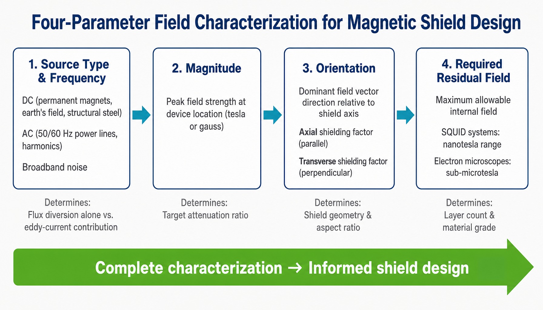
Magnetic shielding design begins with four measurements that constrain every downstream choice.
Instruments and Methods for Ambient Field Mapping
For most applications, the primary tool for a field survey is a calibrated, three-axis fluxgate magnetometer. High-quality instruments like calibrated three-axis fluxgate magnetometers or the Stefan Mayer Instruments FLC series are well-suited for measuring DC and low-frequency AC fields in the microtesla to millitesla range. For stronger fields, a Hall-effect gaussmeter, such as those from Lake Shore Cryotronics, may be necessary. For characterizing environments with extremely low field requirements, SQUID magnetometry systems provide sub-nanotesla resolution.
The measurement procedure is straightforward. Place the three-axis H-field probe at the planned location of the sensitive component. It is essential to use a magnetic (H-field) probe, not an electric (E-field) probe, which is a common procurement error. Record the field magnitude and vector components over a period long enough to capture any time-varying sources, such as a full 24-hour cycle in a laboratory or several power cycles of nearby machinery. This data set provides the baseline against which the shield's performance will be designed and ultimately validated.
Selecting Shielding Alloys by Application Constraints
The right shielding alloy is determined by the intersection of field strength, frequency, operating temperature, and mechanical constraints, not by simply choosing the material with the highest nominal permeability. A critical reality often omitted from datasheets governs this decision: fabrication stress drastically degrades permeability.
Stress-annealed sheets of high-permeability alloys like MuMETAL® (ASTM A753 Alloy 4) have a maximum relative permeability in the range of 10,000–25,000 before fabrication. However, any forming, punching, bending, or welding introduces crystal lattice defects and residual stress that cause permeability to collapse to a range of 100–1,000, as measured per ASTM A773. The shield's magnetic properties can only be restored through a final, controlled dry hydrogen annealing cycle after all mechanical work is complete. This thermal process raises permeability by a factor of approximately 40 to 400.
This fact, that the shield you form is not the shield you anneal, is fundamental. It makes material selection and fabrication planning inseparable.
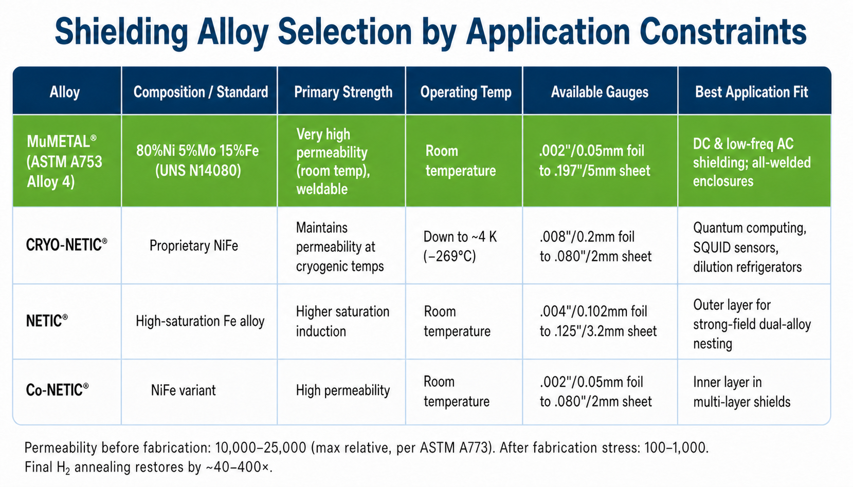
Magnetic field shielding techniques depend on matching alloy properties to application constraints.
MuMETAL® for High-Permeability Room-Temperature Shielding
For a wide range of DC and low-frequency AC magnetic shielding applications at room temperature, MuMETAL® (ASTM A753 Alloy 4) is the most widely specified alloy. Composed of approximately 80% Nickel, 5% Molybdenum, and 15% Iron (conforming to UNS N14080), it offers very high initial and maximum permeability when properly annealed. It is available from Magnetic Shield Corporation from 0.05mm (.002") thin foil to 5mm (.197") thick sheets.
A key fabrication advantage is that MuMETAL® is weldable, so enclosure seams can be joined by welding rather than by mechanical fasteners. Weldability enables the construction of all-welded MuMETAL® enclosures that provide superior magnetic continuity and eliminate the flux leakage paths inherent in bolted or riveted joints. A well-designed MuMETAL® enclosure therefore uses welded seams throughout, with screws or fasteners kept to the minimum needed for mounting. For pre-formed components, deep drawn MuMETAL® cans are available as stock items for common enclosure sizes.
CRYO-NETIC® for Cryogenic and Superconducting Environments
Standard high-permeability nickel-iron alloys lose a significant portion of their permeability at cryogenic temperatures. This makes them unsuitable for shielding superconducting quantum bits (qubits), SQUID sensors, or other sensitive instruments operating inside dilution refrigerators or liquid helium dewars.
CRYO-NETIC® is a proprietary nickel-iron alloy specifically engineered to maintain high permeability at temperatures approaching 4 Kelvin (-269°C). For a quantum computing team needing to attenuate stray fields around a qubit package operating at millikelvin temperatures, the shield must perform at the 4 K thermal stage. CRYO-NETIC® stress annealed sheet , available in gauges ranging from 0.2mm (.008") thin foil to 2mm (.080") thick sheets, maintains its magnetic attenuation in this environment, where standard 80NiFe alloys would become magnetically transparent. Operating temperature is a primary material-selection gate, not an afterthought.
NETIC® for High-Saturation and Strong-Field Applications
Every high-permeability material has a saturation limit. When the ambient field is strong enough to drive the material past the "knee" of its B-H curve, permeability collapses and the shield stops diverting flux effectively. This is a common failure mode in applications near high-current conductors or large permanent magnets.
NETIC® is a high saturation soft iron alloy that has a higher saturation induction than MuMETAL®, making it suitable for attenuating stronger fields without saturating. Its permeability is lower, so it is most effective as the outer layer in a dual-alloy nesting strategy. NETIC® is available in gauges ranging from 0.102mm (.004") thin foil to 3.2mm (.125") thick sheets. The outer NETIC® layer absorbs the bulk of the strong external field, reducing it to a level the inner layer can handle. An inner layer of high-permeability MuMETAL® or Co-NETIC® then provides the final high attenuation of the much weaker residual field. Co-NETIC®, which meets the same standards and specifications as MuMETAL® (such as ASTM A753 Alloy 4), is available in gauges ranging from 0.05mm (.002") thin foils to 2mm (.080") sheets for use as the inner layer in multi-layer shields. This approach ensures an adequate shield saturation margin.
How Geometry, Layers, and Construction Details Determine Shielding Factor
Material selection accounts for about half of a shield's real-world performance. The other half is determined by geometry, layer count, and construction integrity. The shielding factor (S) the ratio of the external field strength to the internal residual field is not a property of the material alone. It depends heavily on the enclosure's shape, its aspect ratio (length-to-diameter), the number of layers, the air gap between layers, and, crucially, the size and treatment of every opening.
A shield made from the best alloy but with poor geometry or unmanaged apertures will be easily outperformed by a shield made from a less exotic material in a well-designed enclosure. Datasheet figures can also mislead in a second way: permeability is not a fixed material constant; it varies with the applied field level, so a shield designed using the maximum permeability value from a datasheet will underperform in any region of the enclosure where the local flux density pushes the alloy away from that peak operating point.
Enclosure Shape, Aspect Ratio, and Multi-Layer Nesting
For a given material thickness, a closed cylindrical or spherical shield will always outperform a rectangular one. The sharp corners of a box cause flux concentration, creating localized regions of lower effective permeability.
For cylinders, the aspect ratio (length divided by diameter) has a profound effect on the axial shielding factor. A long cylinder with closed ends provides substantially higher attenuation for fields parallel to its axis than a short, open-ended cylinder. A cylinder with a 1:1 aspect ratio might deliver less than half the axial shielding factor of an identical-diameter cylinder with a 4:1 aspect ratio, due to field lines re-entering through the open ends.
To achieve very high shielding factors, a multi-layer nested shield is far more effective than a single thick-walled shield. When nesting multiple shield layers, the air gap between layers contributes more to the composite shielding factor than simply doubling the wall thickness in a single layer, because each successive layer operates on the already-attenuated field rather than sharing the full external flux load. The total shielding factor is approximately the product of the individual layer factors, not their sum.
Managing Apertures, Seams, Joints, and Cable Penetrations
A shield is only as good as its weakest point. Ultimately, the shielding factor of an enclosure is limited by its largest unmanaged aperture, not by its wall material. Every hole for cables, connectors, ventilation, or optical access is a potential path for field reentry.
To mitigate this leakage, apertures must be treated with collars tubular extensions that project outward from the shield surface. As a rule of thumb, the collar should extend a distance equal to or greater than the longest edge of the aperture or the hole diameter. This extension acts as a waveguide-below-cutoff for the magnetic flux, attenuating the field that would otherwise leak through.
For seams and joints, all-welded construction, possible with alloys like MuMETAL®, provides the best magnetic continuity. Bolted or riveted joints inevitably have small air gaps at the fastener interfaces, which create high-reluctance paths that allow flux to leak into the shielded volume. If welding is not feasible, an overlapping joint design is preferable to a simple butt joint. Finally, any wire or cable passing through the shield wall must be routed through a properly shielded connector or a collared penetration. Passing a bundle of wires through an open, untreated hole is one of the most reliable ways to compromise an otherwise sound shield design. For guidance on shielding conductors themselves, see our article on magnetic shielding efficiency for wiring applications .
In practice, a correctly built MuMETAL® enclosure is all-welded: every seam is closed by a continuous weld, and screws or fasteners appear only at the few mounting points the installation requires. If a drawing or sample enclosure shows rows of fasteners closing its joints, treat that as a sign that magnetic continuity has been traded away at those seams.
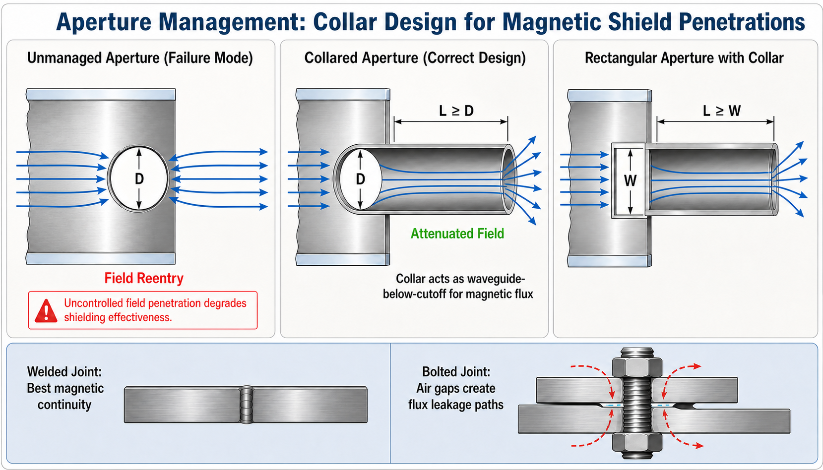
Every aperture needs a collar the detail that most often limits magnetic shielding performance.
Why Post-Fabrication Hydrogen Annealing Determines Real-World Performance
The single most common and critical cause of underperforming magnetic shields is the omission of final annealing after fabrication. As previously stated, stress-annealed MuMETAL® (ASTM A753 Alloy 4) sheet has a maximum relative permeability between 10,000 and 25,000 before it is worked. Every fabrication operation like bending, deep drawing, punching, machining, and welding introduces dislocations and residual stress into the material's crystal lattice. This mechanical damage can reduce the effective permeability to the 100–1,000 range — a fall of one to two orders of magnitude.
Performance is restored by a final heat treatment cycle known as hydrogen annealing. The fabricated shield is heated to a high temperature (typically over 1100°C) in a controlled, dry hydrogen atmosphere and then cooled at a specific rate. This process relieves the mechanical stresses, promotes grain growth, and drives out impurities like carbon and sulfur. The result is a recovery in magnetic performance, with permeability increasing by a factor of 40 to 400, with maximum DC permeabilities measured as high as 800,000.
This is not an optional finishing step; it is the manufacturing step that creates the shield's magnetic properties. The aerospace team from the introduction measures only 8-12 dB of attenuation in part because their shield, though made of the correct alloy, is never annealed after being formed and drilled; the uncollared cable penetrations account for the rest of the shortfall. Without annealing, the part they install retains only a small fraction — as little as 1% — of its potential permeability. Annealing must occur after all mechanical operations are complete. Any subsequent drilling, bending, or even rough handling can re-introduce stress and degrade the shield's performance.
Validating Shielding Effectiveness After Installation
A shield's performance is not proven until it is measured in its final installed environment. While computer simulations using Finite Element Method Magnetics (FEMM) or commercial packages like COMSOL Multiphysics can predict performance, they do not replace physical measurement. A two-stage validation approach is standard practice.
First, the fabricated and annealed shield should undergo laboratory testing to verify its baseline performance. This is typically done by measuring its insertion loss using a Helmholtz coil system, which generates a known, uniform magnetic field. A calibrated fluxgate probe inside the shield measures the attenuated field. This test, often performed according to standards like ASTM A698, confirms that the material, geometry, and annealing process have produced a part that meets the design intent under ideal conditions.
The second stage is an in-situ field survey after the shield is installed in its final operating environment. This is critical because the local magnetic environment may include nearby ferromagnetic structures, time-varying gradient fields, or mechanical stresses not present in the lab. Using a three-axis fluxgate magnetometer, measure the ambient field outside the shield and the residual field inside, with the probe placed at the exact location of the sensitive component. Comparing these two measurements gives the real-world shielding factor. This final check confirms that installation practices, cable routing, and unexpected environmental factors have not compromised the shield's integrity.
From Field Survey to Validated Shield: How Magnetic Shield Corporation Supports the Full Design Sequence
The central argument of this guide is that effective magnetic shielding depends on a sequence of interdependent engineering steps. A failure at any point from an incomplete field survey to skipping post-fabrication annealing can compromise the entire system. This process is difficult to manage when the material supplier, fabricator, heat treater, and test lab are all separate entities with no shared accountability for the final outcome.
At Magnetic Shield Corporation, we manage the full design-to-validation sequence in-house.
Our process directly maps to the engineering sequence described here:
- Engineering & Design: Our applications engineers work with your team to characterize the field environment and translate requirements into a manufacturable design.
- Proprietary Alloys: We manufacture a range of proprietary alloys, including high-permeability MuMETAL® and Co-NETIC®, high-saturation NETIC®, and cryogenic-grade CRYO-NETIC®, ensuring the material is matched to the application's temperature, frequency, and field strength.
- Custom Fabrication: Our in-house fabrication capabilities include precision forming and welding of MuMETAL® enclosures, creating magnetically continuous shields for complex geometries. Fabrication can start from a hand sketch or a full CAD model, as described in sketch, draw, or design a custom shield .
- Hydrogen Annealing: Every fabricated shield undergoes a final, controlled hydrogen annealing cycle to relieve fabrication stress and maximize magnetic permeability.
- Validation: Our ISO 9001-certified quality laboratory is equipped with Helmholtz coils, fluxgate sensors, and other instrumentation to measure shielding effectiveness to standards including ASTM A698 and permeability to ASTM A773 and ASTM A927.
For teams needing to prototype solutions, our magnetic shielding evaluation lab kits provide material samples for hands-on testing.
Contact Magnetic Shield Corporation's engineering team to discuss your field-control requirements and request a custom shielding evaluation.
Conclusion
Shielding a magnetic field is not primarily a question of which alloy to buy. It is a question of how well an entire engineering sequence is executed. From the first fluxgate measurement of the ambient field to the final post-installation validation, each step constrains the next. Skipping a step failing to characterize the source, ignoring fabrication stress, or neglecting to manage apertures is the most reliable way to build a shield that underperforms.
As applications in quantum computing, medical imaging, and scientific instrumentation push toward lower residual-field requirements down to the nanotesla and sub-nanotesla levels the margin for error disappears. In these domains, each step of the sequence must be grounded in measurement and validated before the next one begins.
Frequently Asked Questions
Can magnetic shielding materials be welded without degrading permeability?
MuMETAL® (ASTM A753 Alloy 4) is weldable, and welded joints provide superior magnetic continuity compared to bolted construction. However, welding creates localized stress that reduces permeability in the heat-affected zone. A final hydrogen annealing cycle after all welding is complete is essential to restore full permeability across the entire assembly.
How do I calculate the number of shield layers needed for a target residual field?
First, determine the required shielding factor by dividing the measured ambient field by the target residual field. Then, use analytical formulas or FEA tools like FEMM to estimate the shielding factor of a single layer based on alloy, thickness, and geometry. If one layer is insufficient or would saturate, add nested layers; the total shielding factor is approximately the product of the individual layer factors. For more complex geometries and performance targets, Magnetic Shield Corporation can also perform advanced simulations using COMSOL Multiphysics. You can also use our online magnetic shielding calculator for an initial estimate.
What happens when a magnetic shield reaches saturation, and how do I prevent it?
When the magnetic flux density in the shield wall exceeds the material's saturation induction, its permeability collapses and it becomes magnetically transparent. To prevent this, use a multi-layer shield with an outer layer of a high-saturation alloy like NETIC® to absorb the bulk of the field, and an inner layer of a high-permeability alloy like MuMETAL® or Co-NETIC® to attenuate the remaining weaker field.
How do I specify magnetic shielding for a quantum computing dilution refrigerator?
Specify CRYO-NETIC® sheet for any shield operating at or near 4 K, as standard 80NiFe alloys lose permeability at cryogenic temperatures. Define the required residual field at the qubit location (typically nanotesla-range) to determine the number of layers and nesting geometry. The shield must be fully fabricated and annealed before installation, and only then cooled down to its operating temperature.
What is the cost-performance tradeoff between single-layer and multi-layer magnetic shields?
A single, thicker layer is simpler and less expensive to fabricate. However, a multi-layer shield with air gaps between thinner layers achieves a much higher shielding factor for a given total material mass, as the attenuation is multiplicative. For moderate shielding requirements, a single 1.58mm (.062") MuMETAL® shell may suffice. For very low residual fields, multi-layer nesting is almost always necessary.
What is the difference between magnetic shielding and electromagnetic shielding?
Magnetic shielding specifically attenuates static (DC) and low-frequency magnetic (H) fields by diverting flux through high-permeability materials. Electromagnetic (EM) shielding is a broader term that also includes electric-field shielding (using a conductive Faraday cage) and high-frequency RF shielding (reflection and absorption). A copper box is an excellent EM shield for electric fields but provides almost no DC magnetic shielding.