


Faraday Cage vs. Magnetic Shielding: Why Your Enclosure Fails at Low Frequencies
Posted by Josh Wickler, Vice President of R&D on Oct 21st, 2026
Key Takeaways
- A standard Faraday cage, made of copper or aluminum, is an electric-field and RF shield. It provides virtually no attenuation for DC or low-frequency (e.g., 50/60 Hz) magnetic fields.
- High-frequency shielding relies on eddy currents, governed by skin depth. Low-frequency magnetic shielding relies on flux shunting, which requires high-permeability materials like MuMETAL®.
- Real-world performance of a magnetic shield depends on a final dry hydrogen anneal after all fabrication (forming, welding) to restore the material's permeability, which can be degraded by orders of magnitude from mechanical stress.
- For strong ambient fields, a multi-layer shield is required: a high-saturation outer layer (like NETIC®) to handle the bulk flux, and a high-permeability inner layer (like MuMETAL®) for fine attenuation.
- Apertures, seams, and cable penetrations are primary sources of magnetic flux leakage. Shielding collars and welded seams are critical design details that often determine the final shielding factor.
An engineering team installs a custom copper Faraday cage around a new dilution refrigerator, confirming excellent RF attenuation during commissioning. The system is ready. Then, they turn on their SQUID magnetometers and find the noise floor is unacceptably high. The 60 Hz stray magnetic field from a nearby power transformer is coupling into the sensors at nearly full strength. The cage, so effective against RF, is doing almost nothing to stop it.
This scenario is not a failure of the Faraday cage. It is a failure of application, born from a common misconception in precision instrumentation: the belief that a Faraday cage provides comprehensive electromagnetic shielding.
A Faraday cage is an electric-field and high-frequency shield. It is not a magnetic-field shield for DC and low-frequency interference. Conflating the two leads to redesign cycles and instruments that fall short of their specified performance.
This guide explains the physics of why standard Faraday cages fail at controlling DC and low-frequency magnetic fields. We will cover the frequency-dependent crossover where one shielding mechanism gives way to another, and detail the engineering approach using high-permeability alloys, multi-layer designs, and disciplined fabrication that actually controls the full interference spectrum.
What a Faraday Cage Actually Shields and the Mechanism Behind It
A Faraday cage constructed from a good electrical conductor like copper or aluminum is highly effective at two specific tasks: shielding static electric fields and attenuating high-frequency electromagnetic waves. The physical mechanisms, however, are distinct.
For static (DC) electric fields, the principle is charge redistribution. When the enclosure is placed in an external electric field, mobile charges within the conductor rearrange themselves on the surface. This creates an opposing internal electric field that precisely cancels the external field within the enclosure's volume. The interior is effectively isolated from the external electrostatic environment.
For high-frequency electromagnetic (EM) waves, the mechanism is reflection and absorption driven by eddy currents. The oscillating magnetic component of the radio-frequency (RF) wave induces circulating currents eddy currents in the conductive walls of the enclosure. These currents, in turn, generate their own opposing magnetic field that attenuates the incoming wave.
The effectiveness of this eddy-current shielding is governed by a parameter called skin depth: the distance into the conductor at which the field strength drops to about 37% of its surface value. At 1 GHz, the skin depth in copper is ≈0.002mm — a small fraction of the thinnest 0.152mm (.006") foil gauge. This means even a very thin copper foil provides multiple skin depths of material, resulting in substantial attenuation. An EMC test chamber built with copper or aluminum walls can readily achieve 60 to 100 dB of insertion loss for frequencies above 100 MHz, as measured per the IEEE 299 standard. Within this frequency range, it does exactly the job it was designed for.
The problem arises when engineers assume this high-frequency performance extends down to the magnetic fields produced by power lines, transformers, and permanent magnets.
Why a Faraday Cage Fails at DC and Low-Frequency Magnetic Fields
Here is the direct answer to the question so many engineers ask: does a Faraday cage block magnetic fields? For DC and low-frequency magnetic fields, the answer is no. A standard conductive enclosure made of copper or aluminum provides negligible attenuation below about 1 kHz.
The physics are unambiguous. A static (DC) magnetic field, such as from a permanent magnet or the Earth's geomagnetic field, does not change with time. Because it is not changing, it induces no eddy currents in the walls of a copper or aluminum enclosure. With no opposing field generated, the magnetic flux lines pass through the non-magnetic conductive material as if it were not there.
For low-frequency AC magnetic fields, like the 50/60 Hz interference from building power systems, the situation is only marginally better. The oscillating field does induce eddy currents, but the skin depth at these low frequencies becomes impractically large. At 60 Hz, the skin depth in copper exceeds five times a standard 1.58mm (.062") sheet gauge. A typical enclosure wall of that thickness represents only a small fraction of one skin depth, so the magnetic field penetrates it with little opposition.
When a shielded enclosure specified as a Faraday cage fails to attenuate DC or low-frequency magnetic interference, the typical result is a redesign cycle and repeated qualification testing. Both trace back to the same root cause: specifying a conductive enclosure for a problem that requires magnetic flux shunting. The failure is predictable and, with the right engineering, preventable.
The Frequency Crossover: When Eddy Currents Give Way to Flux Shunting
Shielding effectiveness is not a single number; it is a curve that changes with frequency, and the dominant physical mechanism for attenuation changes along with it. Understanding this crossover is fundamental to selecting the right shielding material.
Above ~100 kHz (Absorption/Reflection): At high frequencies, as discussed, eddy currents in any good conductor provide substantial attenuation. The primary mechanism is absorption loss, governed by the ratio of the wall thickness to the skin depth. A conventional Faraday cage is operating in this regime and works well.
Below ~1 kHz (Flux Shunting): As frequency decreases, skin depth increases, and eddy-current shielding becomes ineffective. In this DC and low-frequency regime, the only effective passive shielding mechanism is flux shunting . This requires a material with high relative magnetic permeability, which provides a low-reluctance path to divert magnetic flux lines around the shielded volume, much like a wire diverts electrical current around a high-resistance component.
This is where magnetically soft, high-permeability alloys become essential. Materials like copper and aluminum have a relative permeability of ~1, the same as air. In contrast, a high-nickel alloy like MuMETAL® (conforming to ASTM A753 Alloy 4 and UNS N14080) can achieve an initial permeability over 20,000 and a maximum permeability over 300,000 — but only in a finished part that has been through a proper final dry hydrogen anneal. As-supplied stress annealed sheet sits well below that, and fabrication drops it lower still. It acts as a "magnetic conductor," actively redirecting the field.
Between these two regimes, from roughly 1 kHz to 100 kHz, is a transitional zone where both eddy currents and flux shunting contribute to attenuation. The key takeaway is this: your shielding strategy must be dictated by the frequency spectrum of the interference you need to control.
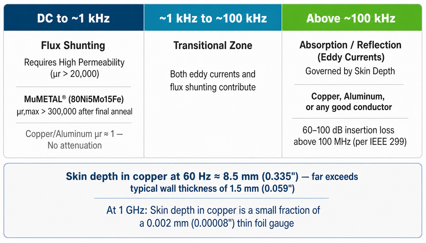
Shielding mechanism shifts from flux shunting to eddy currents as frequency increases.
Designing Multi-Layer Enclosures That Shield Both RF and Low-Frequency Magnetic Fields
When the interference environment contains both high-frequency EMI/RFI and DC or low-frequency magnetic fields, the solution is a hybrid, multi-layer enclosure. This design combines a conductive layer for RF shielding with one or more high-permeability layers for magnetic flux shunting.
However, a successful design is not as simple as wrapping a Faraday cage in a sheet of MuMETAL®. The layer order, material selection for each layer, fabrication methods, and thermal processing are all critical engineering decisions that determine the final shielding factor.
Pairing High-Saturation and High-Permeability Alloy Layers
A single layer of a high-permeability alloy like MuMETAL® can be overwhelmed in a strong ambient magnetic field. Every magnetic material has a saturation point the "knee" in its B-H curve beyond which its permeability collapses and it can no longer effectively shunt flux.
The engineering solution for moderate-to-strong fields is a nested-shell design.
- Outer Layer (High Saturation): The outer shell is constructed from an alloy with a high saturation induction, such as NETIC® , which is a high saturation soft iron alloy. Its job is not to provide maximum attenuation but to absorb the bulk of the ambient flux without saturating itself. It acts as a "flux diverter," reducing the field strength that the inner layer must handle.
- Inner Layer (High Permeability): The inner shell, now sitting in a much weaker field, is made from a high-permeability alloy like MuMETAL® (80Ni5Mo15Fe). Operating well below its saturation point, this layer can use its extremely high permeability to attenuate the remaining residual field down to the very low levels required by sensitive instruments like photomultiplier tubes or electron microscopes.
This layered arrangement keeps each material within the field range it handles best, providing attenuation in strong ambient fields that a single layer would not reach before saturating.
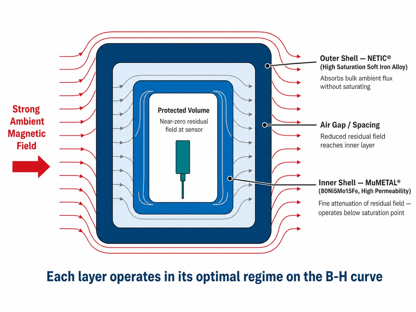
Multi-layer design pairs high-saturation and high-permeability alloys to attenuate strong ambient magnetic fields.
Why Fabrication and Annealing Determine Real-World Performance
Specifying the right alloy is necessary but not sufficient. The magnetic properties of high-nickel alloys are critically dependent on their mechanical and thermal history, so the permeability of a fabricated shield can differ from the as-received value by orders of magnitude.
Any mechanical stress from bending, forming, stamping, drilling, or even aggressive clamping induces dislocations in the material's crystal lattice, which "pin" the magnetic domain walls and drastically reduce permeability. As a result, a shield that is fabricated but not properly annealed may perform little better than a simple steel box.
Consider the numbers for MuMETAL® Stress Annealed Sheet. It starts with a maximum relative permeability of 10,000–25,000 before fabrication. After typical forming stresses, that value can plummet to 100–1,000 when measured per ASTM A773.
To restore performance, a final dry hydrogen anneal is required after all mechanical fabrication is complete. This process, performed at around 1,150°C in a pure, dry hydrogen atmosphere, relieves the internal stresses and allows the crystal grain structure to regrow, restoring the high permeability. A properly annealed part can see its permeability increase by 40 to 400 times compared to its as-fabricated state.
Sequence every weld before the final anneal, never after it.
How Apertures, Seams, and Penetrations Compromise Magnetic Shielding
Even a perfectly layered and annealed shield can be defeated by its openings. Every aperture for access, display, or ventilation, and every seam between panels, creates a high-reluctance gap in the magnetic circuit, allowing flux to leak into the protected volume.
Critically, the amount of leakage is not proportional to the open area of a hole. It is governed by the longest linear dimension of the opening. Magnetic flux fringes from the edges of an aperture, and the larger the opening, the further the field penetrates.
To combat this, a shielding collar or "spout" made of high-permeability material can be fitted around the aperture. For this to be effective, a key design rule must be followed: the collar must extend outward from the enclosure wall by a distance equal to or greater than the longest edge of the aperture or the diameter of a circular hole. This forces the flux to travel a much longer, high-permeability path to get around the collar, significantly reducing leakage into the interior.
Seams between shield panels present a similar challenge. Bolted or riveted joints create air gaps that act as magnetic discontinuities. For maximum performance, continuous TIG-welded seams are preferred, followed by a full anneal of the completed assembly. For cables, shielded conduits or specialized feedthroughs are necessary to prevent them from acting as antennas that carry interference directly into the enclosure. Proper magnetic shielding efficiency for wiring is an often-overlooked detail that directly affects the shielding factor of an otherwise well-designed enclosure.
Material Selection, Fabrication, and Validation for Magnetic Shields
The engineering challenge is clear: effective electromagnetic shielding, from DC through RF, is an integrated system problem. It demands the right material science, application-specific geometry, disciplined fabrication, controlled thermal processing, and empirical validation. Material selection alone does not solve it.
The alloys below map to the frequency-aware design approach described above:
- MuMETAL® (ASTM A753 Alloy 4) for attenuating weak DC and low-frequency fields as an inner layer.
- NETIC® for high-saturation outer layers in strong ambient fields.
- Co-NETIC® (meets the same standards and specifications as MuMETAL®, including ASTM A753 Alloy 4) for high-permeability shielding layers.
- CRYO-NETIC® for shielding in cryogenic environments near 4 K, such as quantum computing and superconducting research systems.
MuMETAL® sheet is available in 1.58mm (.062") thickness and CRYO-NETIC® sheet in 1.5mm (.059") thickness , and either material can be engineered and fabricated from design through final heat treatment. Shielding factors can be predicted before fabrication using COMSOL Multiphysics® simulation or an online shielding calculator. Fabrication covers precision forming, welding, and final dry hydrogen annealing, the step that restores permeability after mechanical work.
Every custom shield can be validated using Helmholtz coil systems and magnetic-field sensors, with testing performed to standards like ASTM A698 and DOD-STD-1399-070 Part 1 . Field measurements are taken with a rectangular or cylindrical sensor probe placed inside the shielded volume to record the residual field.
Read more: Thin, Flexible Magnetic Shielding for Quantum Computing - Magnetic Shield Corporation
Tell us what you’re shielding and at what frequency, and our engineers will tell you whether a conductive enclosure, a high-permeability shield, or a layered combination is the right answer. Contact our engineering team .
Conclusion
A Faraday cage is a purpose-built tool for shielding electric fields and high-frequency EMI. It is not, and was never intended to be, a shield for DC or low-frequency magnetic fields. Treating these problems as one and the same results in enclosures that leave low-frequency magnetic interference effectively unattenuated.
The correct approach is frequency-aware engineering: matching the shielding mechanism to the interference spectrum. This means relying on eddy currents in conductive materials for RF, and flux shunting in high-permeability alloys for DC and low-frequency magnetic fields. Success depends not only on selecting the right materials but on preserving their properties through disciplined fabrication, final annealing, and careful management of every aperture and seam.
As scientific instruments become more sensitive and electronic environments more noisy particularly in quantum technology, medical imaging, and aerospace this distinction between a simple conductive enclosure and an engineered magnetic shield becomes a primary design consideration.
Frequently Asked Questions
1. Can MuMETAL® be welded without losing its magnetic shielding properties?
MuMETAL® is weldable using standard TIG or resistance welding methods, a practical advantage over copper. However, the welding process introduces thermal and mechanical stress in the heat-affected zone, which severely degrades its magnetic permeability. To regain performance, a final dry hydrogen anneal must be performed after all welding and forming operations are complete. An un-annealed weld seam becomes the weakest link in the magnetic shield.
2. What shielding approach works for quantum computing cryostat and dilution refrigerator environments?
Standard high-nickel alloys like MuMETAL® lose significant permeability at cryogenic temperatures. For shielding superconducting qubits or SQUID sensors in environments near 4 Kelvin (-269°C), the approach is to use an alloy formulated to maintain high permeability at cryogenic temperatures, such as CRYO-NETIC® . Shields for dilution refrigerators often use layers of CRYO-NETIC® integrated with the cryostat's thermal stages, sometimes combined with a room-temperature MuMETAL® or MuROOM® enclosure to reduce the ambient field before it reaches the cold components.
3. How do I calculate shielding effectiveness for a multi-layer magnetic enclosure?
Analytical formulas provide good estimates for simple, idealized geometries like concentric spheres or long cylinders. However, for most real-world parts with complex shapes, apertures, and seams, these formulas are insufficient. Finite Element Analysis (FEA) simulation using tools like COMSOL Multiphysics® provides far more reliable predictions. A practical workflow uses an online shielding calculator for initial estimates, then FEA simulation to design and verify complex shield geometries.
4. Does grounding a Faraday cage improve its magnetic shielding performance?
Grounding is critical for the electric-field shielding function of a Faraday cage. It provides a stable reference potential and a path for static charge to drain away. However, grounding has no effect on the attenuation of magnetic fields. Magnetic shielding relies on either flux shunting (permeability) or induced eddy currents (conductivity and skin depth), neither of which is influenced by the enclosure's connection to earth ground. A grounded copper cage will still pass DC magnetic fields unattenuated.
5. How does skin depth affect the minimum wall thickness I should specify for a magnetic shield?
For eddy-current shielding, effectiveness scales with the number of skin depths in the material wall. One skin depth provides about 8.7 dB of attenuation. At 60 Hz in MuMETAL®, the skin depth falls within the range of Magnetic Shield Corporation's thin foil gauges, 0.2mm (.008") to 0.3mm (.012"). This means even these thin foils provide a meaningful eddy-current contribution. However, at these low frequencies, the primary attenuation mechanism is still flux shunting, which depends more on the material's high permeability and overall geometry than on thickness alone.