

EMI Shielding Materials: A Frequency-Dependent Selection Guide for Engineers
Posted by Josh Wickler, Vice President of R&D on Oct 16th, 2026
Key Takeaways
- Frequency Dictates Physics:* Below ~1 kHz, shielding effectiveness (SE) depends on a material's magnetic permeability (e.g., nickel-iron alloys). Above ~100 kHz, SE is driven by electrical conductivity (e.g., copper, aluminum).
- Datasheets Are Not Guarantees:* The high permeability of alloys like MuMETAL® is only achieved after a specific hydrogen annealing cycle. Mechanical work (bending, welding) after annealing can reduce permeability by 50-90%, degrading low-frequency SE.
- Enclosure Integrity Is Paramount:* The installed SE of an enclosure is often limited by seam leakage, cable penetrations, and ventilation holes, not the wall material. A single unsealed aperture can degrade performance by 20 dB or more.
- Multi-Layering Is Required for High SE at Low Frequencies:* To achieve 60+ dB attenuation at 60 Hz, nested shields with engineered air gaps are necessary. A single layer of high-permeability material typically provides only 25-35 dB.
- Compliance Drives Selection:* Your choice of EMI shielding materials is directly constrained by the frequency ranges and test limits of standards like MIL-STD-461G, DO-160, and IEC 61000.
An engineering team specifies a copper enclosure for a sensitive magnetometer, expecting 60+ dB of attenuation. During qualification testing, they discover performance at 60 Hz is under 10 dB. The shield passes comfortably at 1 GHz but fails the low-frequency magnetic field requirements completely. This outcome is not a material defect; it is a physics mismatch. The shielding mechanism that makes copper effective at RF frequencies reflection loss driven by high conductivity is nearly transparent to low-frequency magnetic fields.
When a shielding material is selected based on a generic ranking rather than the frequency content of the actual threat, the resulting test failure during EMC qualification can delay a program by weeks or months and force costly redesigns. Tying material selection to measured SE data, in dB, across the actual threat frequency band avoids that cycle by front-loading the physics into the specification process.
Selecting the correct EMI shielding materials is a frequency-dependent engineering decision. No single material or alloy provides optimal performance across the entire electromagnetic spectrum from DC to GHz. Real-world shielding effectiveness (SE) depends on understanding which loss mechanism dominates at your frequency of concern and ensuring the fabrication, geometry, and post-processing of the shield preserve the material's intrinsic properties.
This guide provides the engineering framework for making that decision, covering:
- Shielding physics by frequency range
- Material-by-material performance data
- Common fabrication and integration failure modes
- Mapping material choices to compliance standards
- Application-specific guidance for aerospace, medical, and research environments
Why Frequency Range Determines Your Shielding Material, Not the Other Way Around
Shielding effectiveness is not a fixed property of a material it is a function of frequency, field type, and distance from the source. The dominant physical mechanism that provides attenuation reverses as you move from the low-frequency magnetic domain into the RF and microwave domains. At frequencies above roughly 100 kHz, SE is dominated by reflection loss and skin-depth-driven absorption, both governed primarily by the material's electrical conductivity. Below 1 kHz, reflection loss from conductivity becomes negligible for magnetic fields, and SE depends almost entirely on the material's magnetic permeability and its ability to provide a low-reluctance path for magnetic flux.
Asking "what is the best EMI shielding material?" without specifying the frequency content of the threat is an unanswerable engineering question. The copper enclosure that failed to shield the magnetometer at 60 Hz was an excellent choice for 1 GHz, but the wrong physical tool for the low-frequency problem. For answers to common questions about material selection and shielding principles, our shielding FAQs provide a useful starting point.
Reflection Loss and Conductivity: Where Copper and Aluminum Excel
Above roughly 100 kHz, reflection loss is the primary shielding mechanism for far-field plane waves and electric fields. This loss arises from the impedance mismatch at the boundary between the air and the shield's surface. High-conductivity metals like copper (5.8 x 10^7 S/m) and aluminum (3.5 x 10^7 S/m) present a very low impedance to the high-impedance incident wave, reflecting most of its energy. A 0.5 mm (.020") copper sheet provides roughly 80-100 dB of SE at 1 MHz (see the comparison table below), most of it through reflection.
Any energy not reflected is attenuated by absorption as it travels through the material. This absorption loss increases with frequency as the skin depth the depth at which the field is attenuated to 1/e (about 37%) of its surface value decreases. For copper, the skin depth at 1 GHz is just 0.002 mm (about 2 µm), meaning even thin foils are effective absorbers.
Absorption via Permeability: Where Nickel-Iron Alloys Become Essential
Near a magnetic source, the wave impedance is very low, so the mismatch with a conductive shield, and therefore the reflection, is minimal. In this low-frequency regime, shielding requires a material that can absorb and redirect magnetic flux lines, which demands high magnetic permeability, not high conductivity.
This is where high-permeability nickel-iron (NiFe) alloys, such as MuMETAL® (conforming to ASTM A753 Type 4), become essential. These materials exhibit high initial permeability (µi) values of 30,000 to 80,000 after proper hydrogen annealing. Instead of reflecting the field, they act as a "magnetic short circuit," providing a low-reluctance path that shunts the magnetic flux lines through the shield material and away from the protected volume. A single 1.58 mm (.062") layer can provide 25-35 dB of H-field attenuation at 60 Hz. In contrast, copper, with a relative permeability of ~1, provides essentially 0 dB of H-field attenuation via absorption at this frequency. For power-line frequency magnetic fields and DC/quasi-static fields, high-permeability alloys are the only viable material class.
EMI Shielding Material Performance Compared: 60 Hz to 1 GHz
The following comparison provides approximate SE values for common material families at representative frequencies. These values assume a continuous enclosure geometry without significant apertures, with proper fabrication and post-processing (e.g., annealing for NiFe alloys). Real-world installed performance is always lower due to seams, penetrations, and geometry effects, which are addressed in the next section. Use this as a selection starting point, not a specification guarantee.
Approximate Shielding Effectiveness (SE) in dB:
| Frequency | 0.5 mm (.020") Copper | 1.0 mm (.040") 80% NiFe (MuMETAL®) | 2-Layer Nested NiFe |
|---|---|---|---|
| 60 Hz (H-Field) | < 5 dB | 25-35 dB | 50-70 dB |
| 1 kHz (H-Field) | ~10 dB | 40-60 dB | 70-90 dB |
| 1 MHz (Plane Wave) | 80-100 dB | ~50 dB | ~50 dB |
| 1 GHz (Plane Wave) | >100 dB | ~40 dB | ~40 dB |
This data illustrates the fundamental trade-off: materials optimized for low-frequency magnetic fields (NiFe) are not the best choice for RF, and vice versa.
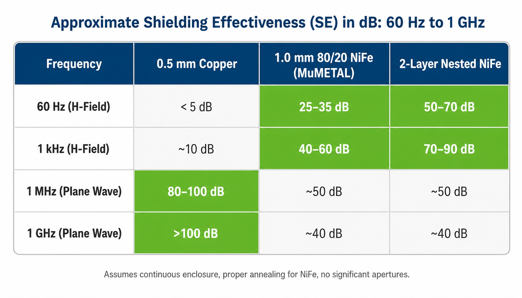
Copper SE ranges from <5 dB at 60 Hz to >100 dB at 1 GHz, while 1.0 mm 80% NiFe provides 25–35 dB at 60 Hz.
Copper and Aluminum: RF and Microwave Shielding Workhorses
For shielding applications above 100 kHz, copper and aluminum are the default engineering choices. Copper's conductivity, the highest of any non-precious metal, makes it the reference material for RF and microwave enclosures. It is ductile, easily formed, and readily soldered.
Aluminum offers about 60% of copper's conductivity but has only 30% of its density, making it the standard for aerospace enclosures and large shielded rooms where weight is a primary design driver. One practical consideration is aluminum's native oxide layer, which is electrically insulating. This can create high contact resistance at seams and gasket interfaces, requiring conductive surface treatments (e.g., chromate conversion coating or nickel plating) or gasket selection that can penetrate the oxide. For commercial electronics where weight is less critical, tin-plated steel offers a cost-effective alternative for achieving moderate SE (40-60 dB) above 1 MHz.
Nickel-Iron Alloys: The Only Option Below 1 kHz
For low-frequency magnetic shielding, 80% nickel-iron alloys like MuMETAL® (conforming to ASTM A753 Type 4) are the primary material. It is critical to understand that these alloys achieve their high permeability only after a specific hydrogen annealing cycle, typically performed at 1100-1180°C in a dry hydrogen atmosphere. Any mechanical work after annealing bending, drilling, or welding can reduce permeability by 50-90% and requires re-annealing.
Where stronger ambient fields risk saturating the shield, 49% nickel-iron alloys are a better choice. They offer a higher saturation flux density (Bsat of ~1.5 T vs. ~0.8 T for 80% NiFe) at the cost of lower initial permeability (typically 5,000-10,000). For applications in quantum computing and superconducting electronics operating at liquid helium temperature (4 K), the room-temperature datasheet permeability of standard 80% NiFe alloys cannot be carried into the design. For any candidate alloy, including cryogenic grades such as CRYO-NETIC®, specify permeability and the resulting SE in dB as measured at 4 K. The selection of a nickel-iron alloy is a decision driven by field strength, operating temperature, and fabrication constraints.
Read more: Thin, Flexible Magnetic Shielding for Quantum Computing
Multi-Layer and Composite Shields: Achieving 60+ dB at Power-Line Frequencies
A single layer of high-permeability material will eventually saturate or reach its shunting limit in a strong magnetic field. The solution is multi-layer nesting. By placing an air gap between two concentric shields, the outer layer reduces the field seen by the inner layer, preventing it from saturating and increasing the total SE beyond what a single layer provides. The comparison table above shows the effect at 60 Hz: two nested 1 mm (.040") 80% NiFe layers roughly double the single-layer attenuation.
For applications requiring 80+ dB, such as zero gauss chambers for research or enclosures for SQUID magnetometers, three or more nested layers may be necessary. The air gap between layers is a critical design parameter, not an arbitrary space. For broadband threats, hybrid constructions combining a conductive outer layer (copper or aluminum for RF) with one or more inner high-permeability layers can address both regimes in a single enclosure: the conductive layer provides reflection loss above ~100 kHz, while the NiFe layers provide flux shunting below ~1 kHz.
Where EMI Shielding Materials Fail in Practice: Fabrication, Annealing, and Aperture Effects
Most shielding failures in fielded systems are not material failures they are integration failures. The alloy specified on the drawing may be capable of 40 dB attenuation at 60 Hz, but the installed shield delivers only 15 dB. This performance gap almost always traces back to uncontrolled fabrication, missed post-processing steps, or geometric discontinuities. The difference between a material's datasheet capability and its system-level performance is where most engineering programs encounter expensive delays.
Consider a scenario where a single-layer enclosure built from 1.6 mm (.062") 80% NiFe (MuMETAL®) sheet would measure 35 dB of attenuation at 60 Hz on the bench, but once installed around a superconducting magnetometer in a basement lab, it would deliver only 15 dB at the same frequency. In this case, the gap would have nothing to do with the alloy: a single unsealed cable penetration and two mounting bolts that locally stress the material past its elastic limit would degrade permeability along the entire bottom seam. Re-annealing the lower shell and adding a ferromagnetic collar around the penetration would restore performance to approximately 35 dB at 60 Hz. Neither fix would require changing the alloy specification.
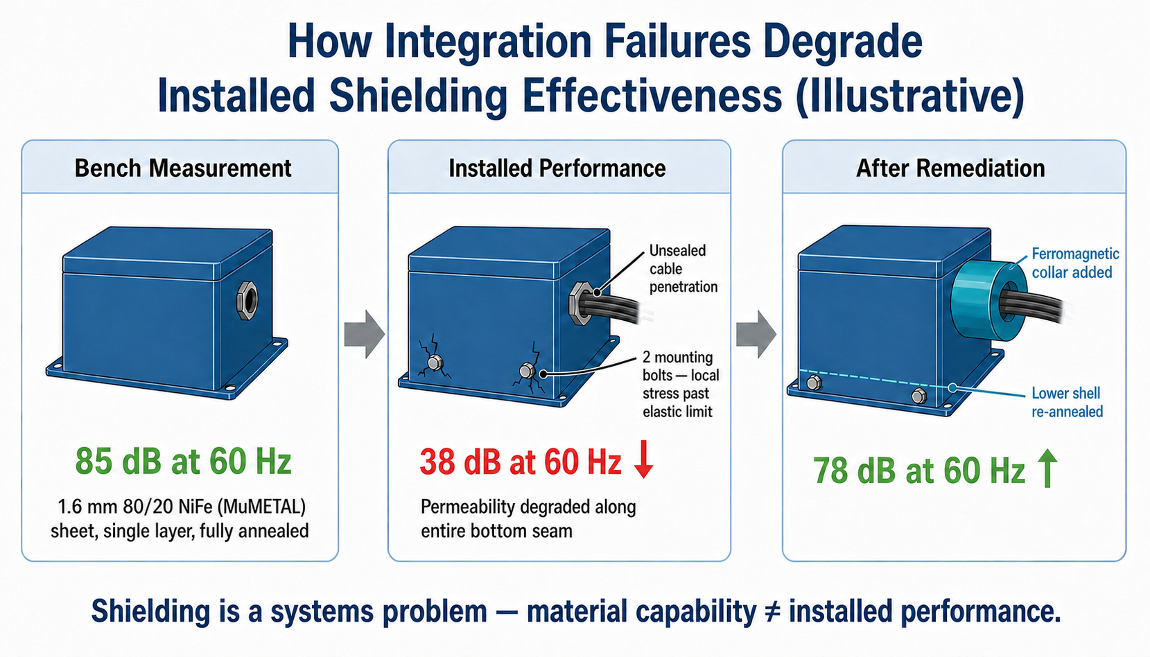
In this illustrative scenario, an unsealed penetration and bolt-induced stress cut 60 Hz SE from 35 dB to 15 dB; re-annealing and a ferromagnetic collar restore it.
Post-Fabrication Annealing and Degaussing: The Steps Most Specifications Miss
High-permeability nickel-iron alloys are magnetically soft. Their high performance depends on a uniform, stress-free crystal grain structure. Raw stress-annealed sheets supplied for fabrication are typically only soft-annealed for ductility, so they do not yet exhibit final shielding performance. Before fabrication, these sheets typically have a maximum relative permeability of about 10,000 to 25,000.
Any forming, stamping, machining, or welding operation introduces stress-induced dislocations that pin magnetic domain walls and further reduce permeability. After fabrication and the added mechanical stresses, relative permeability typically falls to about 100 to 1,000, as measured per ASTM A773 using toroid or ring samples. This is why the final dry hydrogen anneal must be the last major process step after all mechanical operations are complete.
That final dry hydrogen anneal restores the grain structure and increases permeability by roughly three orders of magnitude, or about 40 to 400 times relative to the fabricated condition, bringing the material into its final high-performance shielding state. Specifying a nickel-iron shield without also specifying and verifying this final annealing step on the fabrication drawing is a common and expensive oversight. After annealing, a degaussing cycle removes any residual magnetization that could bias the shield and reduce its effective permeability in low-field conditions.
Seam Leakage and Aperture Control: Where Most Enclosure SE Is Actually Lost
A shielding enclosure is only as good as its worst discontinuity. Seams, joints, cable penetrations, ventilation openings, and access panels create leakage paths that can dominate the total SE, regardless of the wall material's quality.
At RF frequencies, any gap or slot acts as a slot antenna, radiating or admitting energy. A rule of thumb is that an aperture's leakage becomes significant when its longest dimension exceeds 1/20th of the wavelength (λ/20) at the frequency of interest. At low frequencies, any physical gap in a magnetic shield forces the flux lines out into the air, which has a permeability of 1, creating a high-reluctance path that severely degrades the shunting effectiveness.
Ventilation must be designed using waveguide-below-cutoff principles, where openings are configured as an array of small tubes whose length is much greater than their diameter. Removable panels and doors require conductive gaskets to ensure a continuous low-impedance path across the seam. Gasket material must be galvanically compatible with the enclosure material to prevent corrosion, which can degrade SE over the 10-20 year service life typical of aerospace and defense systems.
Read more: Magnetic Shielding Efficiency for Wiring Applications
Mapping EMI Shielding Material Choices to Compliance Standards
An engineer's material selection must ultimately satisfy the specific test limits defined by the program's compliance framework. Different standards impose different frequency ranges, field types, and SE requirements that directly constrain material choice.
- MIL-STD-461G: This U.S. military standard for subsystem and equipment EMC is a common requirement for defense programs. RE102 (radiated emissions, 10 kHz to 18 GHz) and RS103 (radiated susceptibility, 2 MHz to 40 GHz) primarily drive RF shielding needs, typically addressed with aluminum or copper enclosures and proper gasketing. Low-frequency magnetic field requirements, such as RE101 (magnetic field emissions, 30 Hz to 100 kHz) and RS101 (magnetic field susceptibility, 30 Hz to 100 kHz), set test limits that are typically met with high-permeability materials.
- DO-160: This standard for environmental conditions and test procedures for airborne equipment is the civilian aerospace equivalent of many military standards. Section 20 (Radio Frequency Susceptibility) covers 10 kHz to 18 GHz and Section 21 (Emission of Radio Frequency Energy) covers 150 kHz to 6 GHz; both are generally satisfied by conductive enclosures with high-integrity seams.
- IEC 61000 Series: This international standard is prevalent for commercial, industrial, and medical equipment. IEC 61000-4-3 (Radiated, radio-frequency, electromagnetic field immunity test) covers 80 MHz to 6 GHz. IEC 61000-4-8 covers 50/60 Hz power frequency magnetic field immunity, directly driving the need for high-permeability shielding for sensitive medical and scientific instruments.
- IEEE 299: This is the standard method for measuring the shielding effectiveness of enclosures. It provides a repeatable procedure for verifying the installed performance of shielded rooms and chambers, typically from 9 kHz to 18 GHz, with optional extensions down to about 50 Hz for magnetic fields.
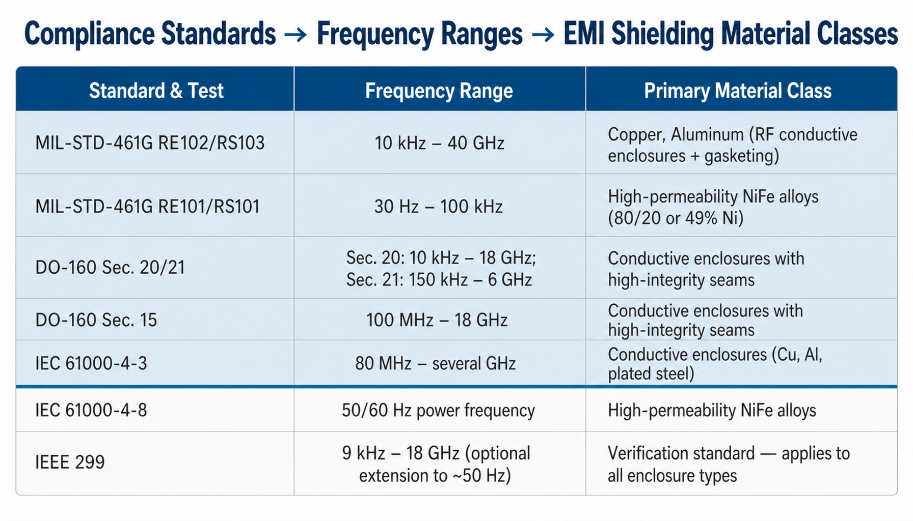
Compliance standards directly constrain which EMI shielding materials an engineer can specify.
Application-Specific Material Selection: Aerospace, Medical, and Quantum Environments
Applying the principles of physics, material performance, failure modes, and compliance leads to distinct selection strategies for different high-stakes applications.
Aerospace and Defense: Thermal Cycling, Corrosion, and Long Service Life
Shielding for aerospace and defense platforms must survive extreme environmental conditions. Wide operating temperature ranges (-55 to +125°C), exposure to salt-fog and humidity, and high levels of vibration and mechanical shock all factor into material selection. Service life requirements often exceed 20 years, ruling out materials or coatings prone to degradation.
Aluminum is often preferred for structural RF enclosures due to its light weight. However, when low-frequency magnetic shielding is required for sensitive avionics or sensor pods, nickel-iron alloys with validated thermal cycling stability must be used. A critical consideration is managing galvanic corrosion between dissimilar metals, such as an aluminum structure and a nickel-iron shield insert. This is typically handled through isolation, protective coatings, or compatible gasket selection validated against environmental standards like MIL-STD-810.
Medical Instruments and Quantum Computing: Ultra-Low Fields and Cryogenic Stability
These two domains share a common requirement: achieving extremely low residual magnetic fields, often below 1 microtesla (µT) or into the nanotesla (nT) range.
For Magnetic Resonance Imaging (MRI) suites, attenuating ambient 60 Hz power-line fields by 30-50 dB is often necessary to prevent image artifacts. This drives the use of room-scale, multi-layer shields made from high-permeability nickel-iron alloys, with performance verified on-site per IEEE 299.
For quantum computing, the coherence of superconducting qubits is degraded by stray magnetic fields. This requires shielding enclosures that not only provide high attenuation but also maintain their magnetic properties at cryogenic temperatures (4 K and below). Room-temperature datasheet permeability values for standard 80% NiFe alloys do not apply at these temperatures, so a cryogenic design must be based on data measured at 4 K. For cryogenic-grade alloys such as CRYO-NETIC®, specify permeability, and the resulting SE in dB, as measured at the operating temperature and after the expected number of thermal cycles between room temperature and 4 K. In these applications, generic shielding alloys are insufficient; materials must be specifically validated for the operating environment.
From Material Selection to Installed Shield: Closing the Engineering Gap
This guide has established that effective EMI shielding is a multi-variable engineering problem. It requires matching material physics to the threat frequency, but success hinges on controlling fabrication, post-processing, enclosure geometry, and environmental survivability. The primary challenge for most engineering teams is bridging the gap between specifying a material and receiving a fabricated, tested, and application-ready shield that performs as expected.
Closing that gap requires controlling every step after material selection. For a low-frequency nickel-iron shield, that means fabrication to the specified geometry, a final hydrogen anneal after all mechanical operations to restore initial permeability to the 30,000-80,000 range, and shielding effectiveness testing of the finished part. Thermal cycling stability, mechanical stress, and corrosion exposure should all be addressed before compliance testing to MIL-STD-461G or IEEE 299.
Whatever the sourcing arrangement, fewer handoffs between material, fabrication, thermal processing, and verification mean fewer points at which unannealed bends, unsealed penetrations, and unverified seams enter a design. Measured SE in dB on the finished shield, rather than the alloy datasheet, then becomes the acceptance criterion. For teams still characterizing an interference problem in an avionics bay, a medical suite, or a cryogenic lab, measuring the ambient field before a shield is designed establishes the baseline against which IEEE 299 or MIL-STD-461G verification and long-term SE stability are judged.
Conclusion
The most important shift in thinking is this: selecting EMI shielding materials is not a search for the "best" material. It is a systematic process of matching material physics to the frequency content of the threat, then engineering the entire shield assembly to preserve that material's performance in the final system.
Frequency determines the dominant shielding mechanism conductivity for RF, permeability for low-frequency magnetic fields. This dictates the material class. But the final, installed shielding effectiveness is governed by factors beyond the alloy itself: post-fabrication annealing, seam and aperture control, gasket integrity, and environmental survivability. These must all be validated against the applicable compliance framework for your program.
As electronic systems become more sensitive and operate in more congested electromagnetic environments, the margin for error in shielding design shrinks. The engineering teams that succeed will be those who treat EMI shielding as a systems engineering problem, not a simple material purchase.
Frequently Asked Questions
Can a single-layer EMI shielding material achieve 60 dB attenuation at 60 Hz?
In practice, a single layer of 80% NiFe alloy in typical thicknesses such as 1.58 mm (.062") provides approximately 25-35 dB of H-field attenuation at 60 Hz. Achieving 60 dB at power-line frequencies generally requires a multi-layer nested construction with engineered air gaps between layers. The exact number of layers depends on source field strength, shield geometry, and the acceptable residual field level inside the shield.
What is the difference between absorption loss and reflection loss in EMI shielding?
Reflection loss occurs at the shield boundary due to impedance mismatch and depends primarily on conductivity; it is most effective against electric fields and plane waves at high frequencies. Absorption loss occurs as the wave's energy is converted to heat while traveling through the shield material; it depends on conductivity, permeability, and thickness relative to skin depth. For low-frequency magnetic fields, reflection loss is minimal, and absorption via high-permeability flux shunting becomes the dominant mechanism.
What electromagnetic shielding material resists galvanic corrosion in salt-fog environments?
Galvanic corrosion risk depends on the electrochemical potential difference between dissimilar metals in the presence of an electrolyte. Tin-plated steel and nickel-plated surfaces reduce this potential difference relative to many bare mating metals, but their salt-fog durability depends on plating integrity and the specific metal pairing. When joining dissimilar metals, such as an aluminum enclosure with a nickel-iron shield, isolation gaskets or compatible surface treatments are necessary. Material selection for salt-fog environments should always be validated per MIL-STD-810 or an equivalent environmental testing standard.
How do I calculate the required shielding effectiveness for a medical MRI suite?
First, measure the ambient magnetic field at the MRI location, typically dominated by 60 Hz power-line fields. Next, find the maximum allowable residual field at the magnet isocenter from the MRI manufacturer's site planning guide (often 0.1-0.5 µT at 60 Hz). The required SE in dB is 20 * log10 (Ambient Field / Allowable Field). This calculated value should be verified by measuring the installed room's performance using IEEE 299 procedures.
How does skin depth change with frequency for copper versus nickel-iron alloys?
Skin depth decreases with increasing frequency, conductivity, and permeability. For copper, skin depth is ~8.5 mm (.335") at 60 Hz, but only ~0.066 mm (.0026") at 1 MHz. For an 80% NiFe alloy with a relative permeability of 50,000 and a conductivity of about 1.7 x 10^6 S/m, the skin depth at 60 Hz is approximately 0.2 mm (.008") far thinner than copper at the same frequency. This illustrates why thin nickel-iron shields are effective absorbers at low frequencies where impractically thick copper would be needed.
What conductive gasket materials maintain EMI shielding integrity over a 20-year service life?
For long-term reliability in aerospace and defense, beryllium copper finger stock and knitted wire mesh gaskets are common choices because they resist compression set, and the maximum allowable compression set and its test condition should be specified on the gasket drawing. Conductive elastomers provide both EMI shielding and environmental sealing at installation, but their SE can degrade under sustained compression or UV exposure. Gasket shielding performance should be validated per SAE ARP 1705, and galvanic compatibility with the enclosure material should be confirmed separately through environmental testing such as MIL-STD-810 salt-fog exposure.